My lure test tank is coming along well. I received the parts from QC Supply. a very good reputable company, but the elbows were not in stock and had to be made, hence I had to wait a little.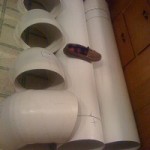 I used 12 inch pvc air duct, and it’s not for intended for high pressure application, but ideal for this “no pressure” lure test tank. It’s actually a lot heavier than I expected at schedule 50.
My boys had lots of fun with this pipe before I assembled it, but it’ expensive just for toys for kids. 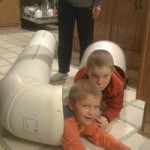 The (2 ) 5 foot lengths plus 4 elbows costed over $300 with shipping so it’s not a cheap project. I bought the glue from Ace Hardware and even though the directions said for up to 8″ PVC, I used it for my 12″ and it worked fine. You just have to work fast AND make sure everything fits dry before applying glue. The only thing is, I wish I would have bought the cleaner specifically formulated for cleaning PVC because the isopropyl alcohol that I used does not quite do it.
The straight pipe comes in 10 foot lengths, so I had the factory cut them into (2) fives, then I cut 6” off of each one for the end of tank, so my longest straight run is 4’6”. This gives the water a pretty smooth flow by the time it gets to the other end where the lure is tested. After dry fitting all the parts, I marked and cut a slot for the electric motor shaft to go though and set the height of the motor so that the prop was centered. The joint near the motor AND opposite (kitty corner) of the motor are not glued with PVC cement enabling me to be able to dis-assemble the tank for easy transport. (I may want to move it to the cottage next summer.) I did caulk them with silicone so that they hold water though. By the way, silicone is not a good substitute for PVC glue since it really does not stick to PVC, but for a semi-permanent joint it works ok.
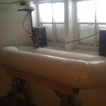 Once all of the parts were glued, I left the whole assemble alone for 24 hours to allow the glue to set. The next day I marked and cut the access hole as shown. This is where we access the lure to be tested, attached to a line with a ball bearing snap swivel.
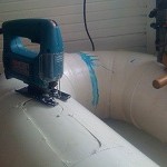
Next, I propped up the “access side” of the tank so that the “motor side” has solid water and the water level is slightly lower on the access side. I’m not yet sure if this is necessary, but I thought the water flow would be more smooth with this set-up.
After filling with water, I wanted to know how fast the water would move with various settings on the electric trolling motor. I used my Depth Raider speed and temperature probe for this with the display powered by a 12 volt wall power pack that just happened to have the right male connector. My motor just has 4 forward settings, so it’s not infinitely adjustable. I was reading .5 mph with my motor setting on 1, 1.2 mph with the setting on 2 and about 2 mph with the setting on 3. Since I had used this probe for a few years on my boat, I know that it reads about .6 mph low when compared to my GPS speed, so adding .6 to the above readings I get 1.1mph, 1.8 mph and 2.6 mph. I am more concerned with the low end anyway so most of my testing is on the 2 lower settings, and knowing these settings, I do not need to have the probe installed permanently. I would be nice to have an infinitely variable motor with a better permanently affixed speedometer, but I can do without it for my testing.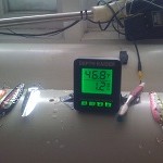
Now for the fun part… testing lures. I use a 20 lb monofilament line, the same as my leader line when trolling, with a ball bearing snap swivel with a wider, rounded end which is important to see the real action without restriction. If no swivel is used the line will twist up and prevent natural rotation and you will get a bad read. In fact the best set-up is to have your swivel about 1 foot up from the lure with a wide, non-restricting wire snap on the lure. My access hole is only 8 inches long, so I drilled a couple of holes on the top, upstream for my fishing line at various distances so my lure rides roughly in the center… heavier lures require shorter lines to stay off the bottom at low speeds. You could also cut a long access hole, but I have not done that yet, since I wanted to be sure before cutting larger holes.
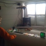
My 6 year old Bruce had fun with me testing some of my favorite lures. He then showed his older brothers how it works.
Next I plan to install a plexiglass window in the side of the tank because it’s hard to observe through the moving water from above. I will post more and perhaps also do a video of it when done
Lure test tank
My lure test tank is coming along well. I received the parts from QC Supply. a very good reputable company, but the elbows were not in stock and had to be made, hence I had to wait a little. I used 12 inch pvc air duct, and it’s not for intended for high pressure application, but ideal for this “no pressure” lure test tank. It’s actually a lot heavier than I expected at schedule 50.
My boys had lots of fun with this pipe before I assembled it, but it’ expensive just for toys for kids. The (2 ) 5 foot lengths plus 4 elbows costed over $300 with shipping so it’s not a cheap project. I bought the glue from Ace Hardware and even though the directions said for up to 8″ PVC, I used it for my 12″ and it worked fine. You just have to work fast AND make sure everything fits dry before applying glue. The only thing is, I wish I would have bought the cleaner specifically formulated for cleaning PVC because the isopropyl alcohol that I used does not quite do it.
The straight pipe comes in 10 foot lengths, so I had the factory cut them into (2) fives, then I cut 6” off of each one for the end of tank, so my longest straight run is 4’6”. This gives the water a pretty smooth flow by the time it gets to the other end where the lure is tested. After dry fitting all the parts, I marked and cut a slot for the electric motor shaft to go though and set the height of the motor so that the prop was centered. The joint near the motor AND opposite (kitty corner) of the motor are not glued with PVC cement enabling me to be able to dis-assemble the tank for easy transport. (I may want to move it to the cottage next summer.) I did caulk them with silicone so that they hold water though. By the way, silicone is not a good substitute for PVC glue since it really does not stick to PVC, but for a semi-permanent joint it works ok.
Once all of the parts were glued, I left the whole assemble alone for 24 hours to allow the glue to set. The next day I marked and cut the access hole as shown. This is where we access the lure to be tested, attached to a line with a ball bearing snap swivel.
Next, I propped up the “access side” of the tank so that the “motor side” has solid water and the water level is slightly lower on the access side. I’m not yet sure if this is necessary, but I thought the water flow would be more smooth with this set-up.
After filling with water, I wanted to know how fast the water would move with various settings on the electric trolling motor. I used my Depth Raider speed and temperature probe for this with the display powered by a 12 volt wall power pack that just happened to have the right male connector. My motor just has 4 forward settings, so it’s not infinitely adjustable. I was reading .5 mph with my motor setting on 1, 1.2 mph with the setting on 2 and about 2 mph with the setting on 3. Since I had used this probe for a few years on my boat, I know that it reads about .6 mph low when compared to my GPS speed, so adding .6 to the above readings I get 1.1mph, 1.8 mph and 2.6 mph. I am more concerned with the low end anyway so most of my testing is on the 2 lower settings, and knowing these settings, I do not need to have the probe installed permanently. I would be nice to have an infinitely variable motor with a better permanently affixed speedometer, but I can do without it for my testing.
Now for the fun part… testing lures. I use a 20 lb monofilament line, the same as my leader line when trolling, with a ball bearing snap swivel with a wider, rounded end which is important to see the real action without restriction. If no swivel is used the line will twist up and prevent natural rotation and you will get a bad read. In fact the best set-up is to have your swivel about 1 foot up from the lure with a wide, non-restricting wire snap on the lure. My access hole is only 8 inches long, so I drilled a couple of holes on the top, upstream for my fishing line at various distances so my lure rides roughly in the center… heavier lures require shorter lines to stay off the bottom at low speeds. You could also cut a long access hole, but I have not done that yet, since I wanted to be sure before cutting larger holes.
My 6 year old Bruce had fun with me testing some of my favorite lures. He then showed his older brothers how it works.
Next I plan to install a plexiglass window in the side of the tank because it’s hard to observe through the moving water from above. I will post more and perhaps also do a video of it when done.

 Brian Helminen

